
Amir Audio Believes AC Quality, Grounding and System Wiring are so Important to have good Sound.
Please Read this article from FM Acoustics (Technical Bulletin No.5 Grounding Rules) :
FM Acoustics Technical Bulletin No.5 Grounding Rules
Important Information: Please read before connecting your equipment.
Attention: Only experienced engineers should attempt to do the checks described below.
Initially both earth and ground must be defined.
Earth is used to describe the ground from the power company. The heavy ground wire brought into the building and grounded to the breaker box is earth. This should be the only interconnection to the outside world from the studio or audio installation. Frequently the ground for the water pipe ground is tied to the same point. In most communities such a water pipe ground connection is a legally required. If you are in doubt, check with your local power company.
Ground is a relative term. It is the name given to that point which is called the zero signal reference. It is the zero signal reference only if all equipment ties to this exact point and has, at least theoretically, absolute zero-Ohm resistance. There must be only one ground point in the entire installation and/or studio complex. Grounding is possibly the single most important characteristic for system stability. Each individual installation may initially look and react differently, but there are common rules which assist in finding the proper grounding system. All hum and buzz, and many of the RFI problems in installations, start with the AC mains and their relationship to ground. The AC power wiring, the light fixtures, the power cords and virtually all other equipment connected to the AC line project both an electrostatic and an electromagnetic field which can be picked up by the audio wire and/or the audio circuitry. Furthermore, AC mains are a carrier for many forms of Radio Frequency Interference (RFI) generated by radio transmitters, electric motors, refrigerators, SCR dimmers, computers and almost all other electric appliances. The effects of these fields on the audio installation must be minimized. Careful design of the system as well as quality control of the actual electrical work is very important for optimal results.
The ground should only be tied to earth by one single interconnection from the zero signal reference to the power company ground. This should be a very heavy stranded copper wire, AWG 5 or even larger. In several studios FM ACOUSTICS’ FORCELINES have been used in order to improve grounding (reducing resistance). In a recording studio control room the best point at which to make the zero signal reference is often the ground plate on the mixing console (if it is massive enough). Otherwise, one should use a high-power buss strip and carefully wire up all the grounds to this point.
In order to give an idea of the importance of proper ground connections: when moving one of the wires tied to the central ground connection of the FM 2001 A by just 1 cm, one can already measure increased hum and a potential difference between the two connections! Remember that this is an extremely massive copper bar with a square section of 5 x 10 mm and is tightened to the post connections with torque-sensitive screwdrivers!
A further example: If a wire of 10 mOhm resistance carries 1 mA of current, it will already generate a voltage of 10 uV (= -100 dB below line-level). If this signal is applied to 8 microphone pre-amplifiers with 40 dB of gain, the resulting signal will be almost 30 dB above the tape noise of an analog tape machine!
Avoid running AC power parallel to or near audio wiring. AC wires radiate magnetic fields with an intensity that decreases proportionally to the square of the distance.
If at all possible, isolate your room from both the power company and all other general purpose electrical wiring in the building. The easiest way to accomplish this is to ask the power company for a separate power transformer and a separate electrical service from their service pole. Obviously, in certain buildings this may not be possible. In such a case you should in-stall an isolation transformer, or better yet a combination of isolation transformer and voltage stabilizer; this unit must be equipped with a Faraday shield which is connected to the secondary ground side.
There are different power line formats in different parts of the world. Three-phase power – which is found in larger buildings – should be avoided, as it is usually connected to air conditioning and other high-power equipment. Preferably a single phase of power dedicated solely to the audio system control room should be used. To this phase no non-audio appliances should be connected.
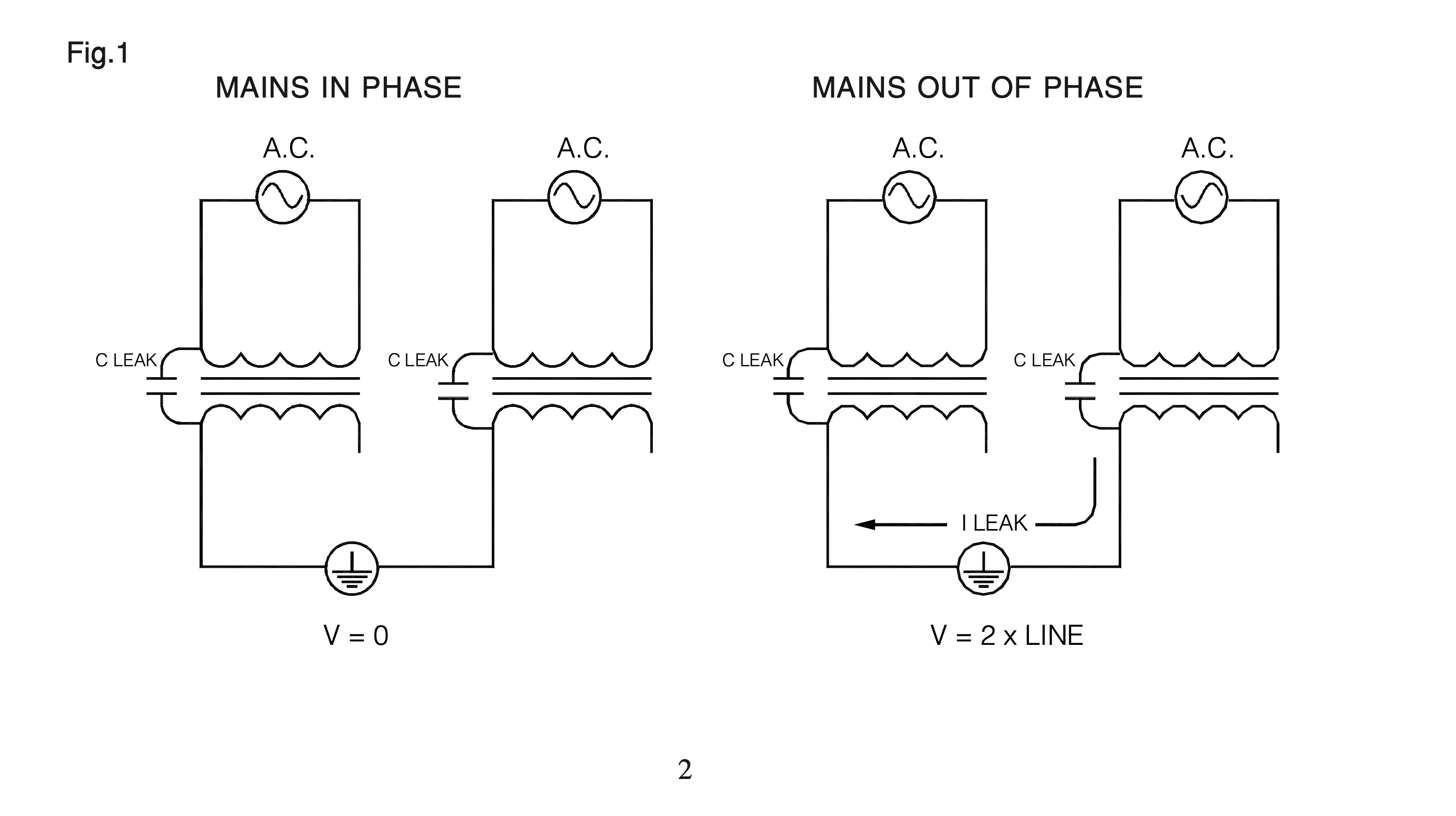
The power transformers in electronic equipment still have a small capacitive coupling between the case and the AC line. If connected to another piece of equipment running on a different phase power line, an electric current will flow in the ground between the two pieces (see fig. 1). Therefore, it is important that all AC outlets for audio are wired to the same phase of the AC line. It is easier to do this when using a single-phase output winding on the dedicated isolation transformer.
Step By Step System Grounding
1) One single system ground must be chosen.In most cases the single system ground will be the third wire of the mains cable, the earth wire. Never jump a ground wire from one piece of equipment to another and then back to the system ground.It should be remembered that in many buildings the earth is not really a true earth, which means that your system is not properly grounded. Wherever possible a separate ground is recommended, consisting of a copper bar sunk deep into the earth. Especially in dry areas the bar should extend several meters into the earth in order to make sure that it contacts humid soil.
2) If there is a heavy or rapidly changing load on your power circuits, then the third wire of your AC supply is not a good system ground.
3) Under no circumstances should air conditioners, refrigerators, fan motors, coke ma- chines, fluorescent lights, etc. be connected to the same power circuit as the monitoring equipment. For these appliances use a separate circuit from a different power supply, or at least a phase of the mains supply which is different from that with which the audio/ control room is powered; this will help that no extraneous noises will enter the audio power lines.If possible shield all of the AC power wires and isolate them from audio equipment. Never run AC power in parallel with audio wiring.
For ultimate results, insist that your power company disconnect, clean and then reconnect all outside contacts at least once a year. Corrosion can cause considerable RF and noise on your power circuit.
4) Install your system so that no groundloops can occur. Groundloops occur when there are two or more DC paths from a device to a system ground. (This might be the case if two devices are connected through a metal chassis as well as through audio circuitry, unless both chassis are lifted from ground).Make sure that all ground potentials are “0”. Again and again we find installations that show a voltage difference between grounds are found. This is dangerous and any equipment drawing some power cannot be guaranteed to run optimally.
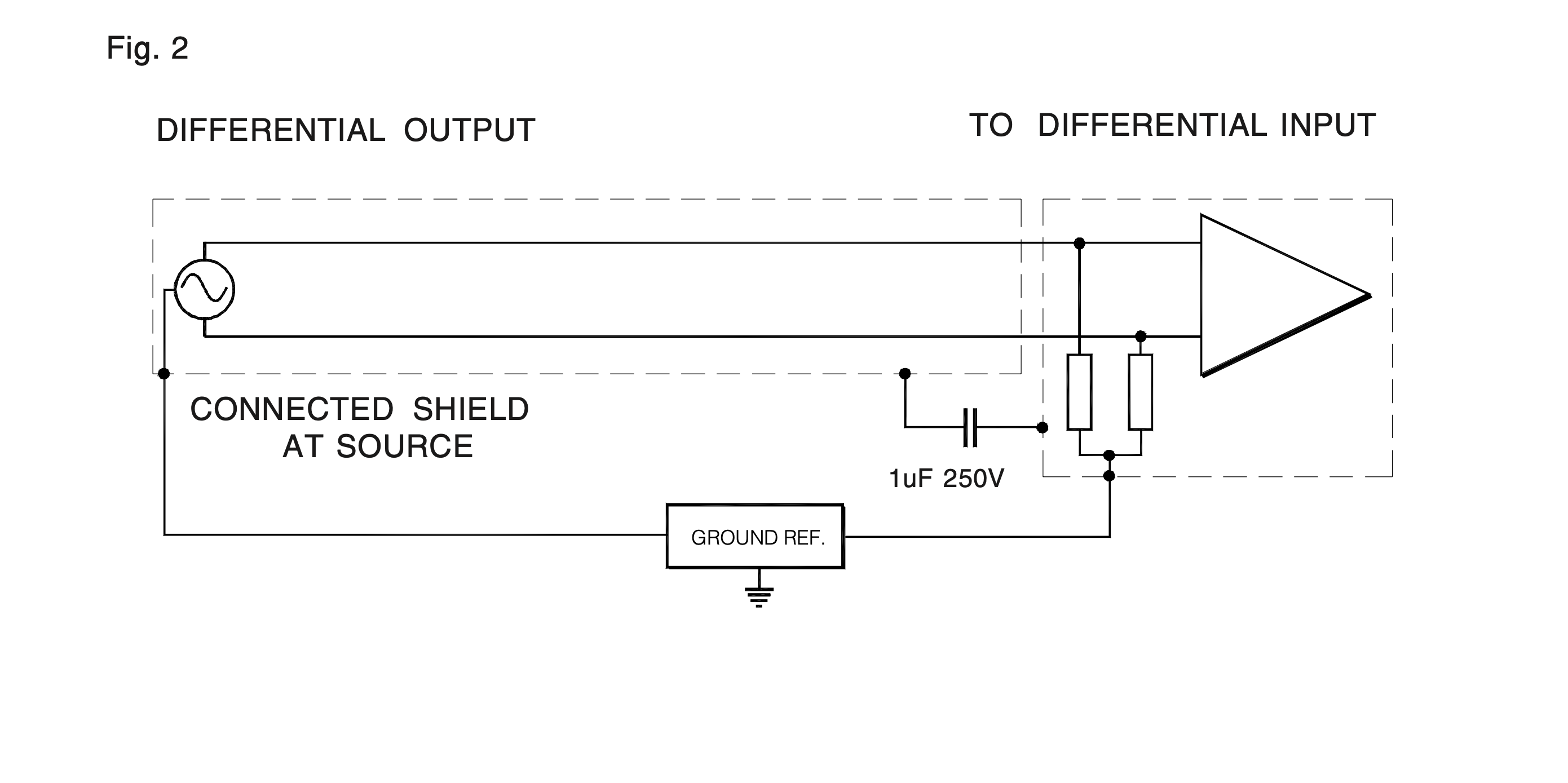
5) In high RF areas one end of the cable must be connected to the chassis of the device through a 0,1 uf 250V capacitor (see Fig. 2). These capacitors may be installed at either end of the line, but they should not be installed in microphone lines. Any line which is not DC isolated at one end may cause an unacceptable groundloop.
Never connect the metal housing of an XRL connector to pin 1 (ground).
6) Devices with unbalanced inputs be fed from an unbalanced output in order to minimize spurious oscillations. When feeding an unbalanced input from a balanced output, the output must be unbalanced. Connect the low side of the output to ground at the balanced output end of the line (Fig. 3).
Attention: Before shorting one signal line to ground make absolutely sure that the output of the unit is truly balanced Equipment that employs simple phase inversion outputs cannot be connected this way.
Fig. 3

7) Never combine grounds except at the system ground. If your components are rackmounted, one of them should be connected to a single ground wire going to the system ground. If some of the products have a “groundlift” feature, this feature should be used and another system ground may be added. All products manufactured by FM ACOUSTICS since 1980 have a groundlift switch on the back panel or are internally groundlifted, thus disconnecting the units internal ground from the third mains wire. The earlier later series of the FM 600A and the FM 800A have no connection between the chassis/third mains wire and the internal electrical ground; this prevents groundloops.It is important that separate racks are not daisy-chained. Make sure that on all XLR connectors none of the pins touch the metal cover, otherwise there will again be the chance of a groundloop.
Be sure to make all shield connections first, leaving chassis ground wires disconnected until the following tests have been completed:
a) Disconnect all power plugs. With an Ohm-meter test the resistance between each chassis in the system. You should always find a high resistance reading between the units. However, be aware that anodized front and back panels may act as an insulator, so make sure that when measuring you connect the Ohm meter to a non-anodized part (e.g., a screw) that makes good contact with the chassis.
b) If your third wire is a satisfactory ground all units have a high resistance reading between their chassis and all units with a groundlift feature have a three wire power cable, then your grounding system may now be complete. However, please note that using the “third wire” grounding system you break the first rule of grounding: The third wire usually goes from one mains plug to another, so that each component does not have a separate ground wire going straight back to the exact system ground! However, in most installations this system will work fine.If excessive noise or hum are present in your system when using a third wire ground, start removing third wire grounds from one component after another until you find the culprit.
8) For better RF and noise shielding, however, one of the components in your rack should be grounded. If an unbalanced unit without a groundlift feature is installed in the same metal rack as the FM ACOUSTICS power amplifiers or crossovers, the unit’s third mains wire must be disconnected beforehand. It will be earthed through the metal rack – and then through the third wire of the unit that is grounded.The above checks will rarely take more than half an hour, but in this fashion you can assure that your installation is functioning correctly. Grounding faults most often create problems with equipment consuming high-power, e.g.: high-power amplifiers, large (mixing desk) power supplies, etc. If you experience recurring problems with such equipment, there could be a groundloop within the installation (something which is often not immediately obvious). Have the above checks performed by a qualified engineer. It will certainly pay off.